Bringing an analog voltage Arduino shield to life
One of the Rascal accessories I've been working on for scientists is what I call the Precision Voltage Shield. It's a circuitboard that plugs into the Rascal or an Arduino that allows you to measure 8 voltages very precisely. Yesterday, I got the precision voltage shield working as an 8-channel digital multimeter with an Arduino. I wanted to record some of the details of how I got working for posterity.
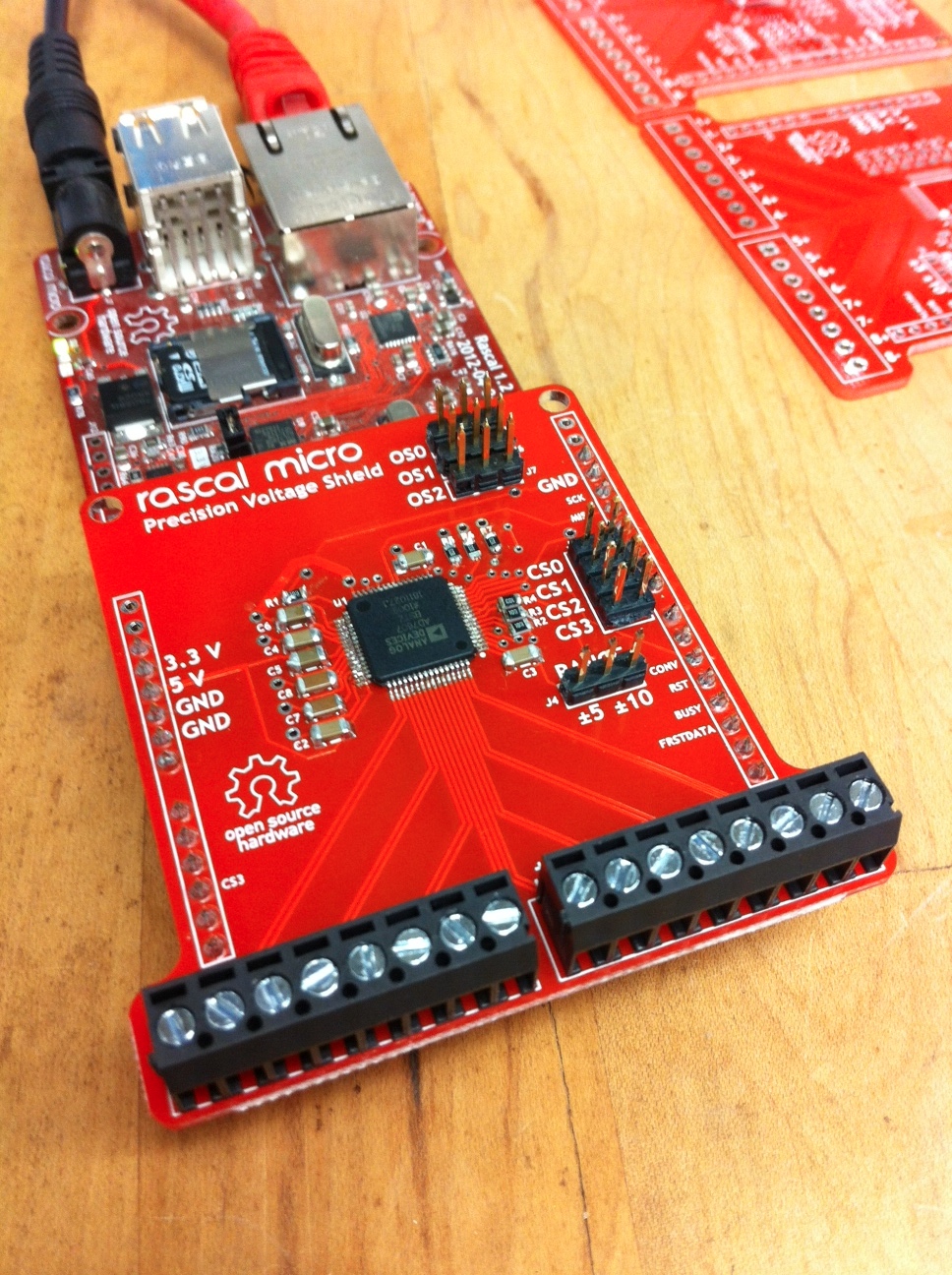 ##### Here's what the precision voltage shield looks like plugged into a Rascal. What a handsome devil! #####
An overview of how the AD7607 A/D converter works
The core of the precision voltage shield is the Analog Devices AD7607 analog-to-digital converter. This chip measures 8 channels with 14 bits of resolution. There are also 16-bit and 18-bit versions, but they cost a little more. I'll probably offer variants of the shield that use those chips if people are interested.
The AD7607 has some awesome features that make it better than a classic A/D converter like the ADC0805. The first is the input filtering it includes. When you sample a voltage repeatedly over time, you run into the problem of aliasing, where high-frequency noise exceeds twice your sampling frequency, which makes it appear like low-frequency noise. Once you've sampled it, you can't tell whether it was high-frequency noise aliased down, or real low-frequency noise, so no digital filter can help you.
The fix for aliasing is an analog filter on each input. Older A/D chips didn't have this because we didn't know how to make capacitors inside chips cheaply. Analog Devices has apparently figured this out; their datasheet claims that each channel has an analog second-order Butterworth filter that attenuates noise over 15 kHz or so. (The 3 dB point changes slightly depending on the input range selected.)
The second cool feature is adjustable oversampling. In its default configuration, when you ask the precision voltage shield for a reading, it samples 64 times and gives you back the average reading. If you want, you can cut the traces under the OS0, OS1, and OS2 jumpers to configure the sampling rate to be higher, but there's no sense in doing that unless you can actually store data at significantly higher data rates than 1 kHz. (See the notes about speed further down for some more thoughts on this.)
The third excellent feature is the adjustable input range. With a jumper on the shield, you can choose whether the input range is +/-5 V or +/-10 V. This means that you can handle large voltages while still being able to read smaller voltages accurately if you need to.
How measurements actually work
To make the shield take a measurement, you pulse pin 5, which is labeled "CONV." The shield will answer by raising its "BUSY" line for around 300 microseconds. After this, the Rascal or Arduino can read the data out using the SPI protocol on "MISO" (pin 12). The oscilloscope screenshot below shows two full cycles of voltages being read. The gap between conversions (around 1 millisecond) is the time it takes for the Arduino to send the raw data to my laptop over USB at 115200 bps. With this gap, the system cycles at 735 Hz. The precision voltage shield Arduino code that I wrote for testing is up on Github. (You are welcome to use it however you like, but I would appreciate a link back to rascalmicro.com.)
- BLUE: start conversion pulse
- PURPLE: busy during conversion
- YELLOW: digital data coming out via SPI
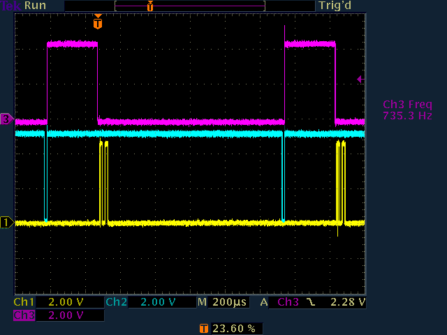 ##### The precision voltage shield talking to an Arduino, captured on my trusty oscilloscope. #####
The AD7607 data format
The AD7607 spews out eight 14-bit measurements sequentially, each ranging from -8192 to 8192 to represent either -5 to 5 V or -10 to +10 V, depending on how the range jumper on the shield is set. The readings are encoded as the two's-complement of the count.
Sampling speed
By default, the precision voltage shield oversamples by 64x and averages the values. As mentioned earlier, you can speed this up if you want, but you need a way to store the data.
The Arduino Uno I was using to talk to the shield has 32 kB of flash memory. If the Arduino pulls 8 readings at around 1 kHz and stores each reading in 2 bytes, that's 16,000 bytes per second, which means that the Arduino is full in 2 seconds. Some scientists do experiments that last less than two seconds, but many (most?) last much longer, which means we need a way to get data out of the Arduino.
I tried two different methods of sending the data: raw and formatting the 14-bit fields into ASCII characters separated by commas. The formatting makes the sampling around 3 times slower (200 Hz or so, rather than 735 Hz), but the limiting factor there was the Arduino's serial transmission rate. By default, the Arduino's serial library can only transmit at 115200 bps. From what I've read on the Arduino forums, an adjustment to the UART divider can get you up to 1 Mbps serial transmission, which should take the raw data transmission time from 1 ms to around 100 us. Adjusting oversampling to just 4x should get the conversion time down to 20 us, which means you're getting averaged samples every 200 us or so, which is equivalent to 5 kHz. To go faster than that, you could reduce oversampling further, speed up SPI (risking data corruption), and switch to a parallel data transmission scheme to get data out of the Arduino faster. In the right circumstances, the AD7607 can sample at 200 ksps, but actually achieving that would take some work.
The other obvious possibility is using something more powerful than the Arduino, like the Rascal. The Rascal's processor is 25 times faster than the Arduino Uno's, and it has an SD card for storage, so the delay incurred by sending the data out the serial port is avoided. When data does need to be transmitted, it has a 100 Mbps Ethernet port.
Next up: the precision voltage shield with a Rascal . . .