Delayed by memory timing errors
(This is a pretty technical post, so if that's not your bag, the summary is that there was a problem with the last round of boards, so I'm making a new version that works. Back to the story.)
When I got two new Rascal prototypes back from the assembler last month, I was pretty excited. The new version, Rascal 1.1, cleans up a bunch of little annoyances and adds new features. The previous batch had sold out quickly and, even better, the Rascal was living up to my vision of a relatively easy-to-use board for connecting stuff to the internet.
After some testing, all the new features-- USB ports, the new JTAG port, and the like-- appeared to work well. Unfortunately, there was a problem with the Rascal's RAM, which meant that when the Rascal tried to write data to certain addresses, the data was lost. If that data turned out to be code that was later executed, the Rascal would choke and reset when it tried to execute whatever random data happened to be there before the failed write.
This all seems straightforward in retrospect. In futuro-spect, it took me about a week to narrow down the problem to failing RAM writes.
Figuring out the cause
After watching the board reset a few times, I tried logging the boot messages to see when resets occurred. Some tedious tallying yielded this table of last boot messages from the Linux kernel before reset occurred.
Reps  Message
----  ------------------------------------------------
1     Uncompressing Linux... done, booting the kernel.
4     RPC: Registered tcp NFSv4.1 backchannel transport module.
2     INIT: version 2.86 booting
1     mount: mounting /dev/mmcblk0p1 on /mnt/root failed: . . .
4     Setting up IP spoofing protection: rp_filter.
2     Lease of 192.168.10.190 obtained, lease time 43200
1     udevd (403): /proc/403/oom_adj is deprecated . . .
1     * Starting Avahi mDNS/DNS-SD Daemon: avahi-daemon...done.
2     Populating dev cache
1     INIT: Entering runlevel: 5
14    rascal14 login:
My fellow Artisan's Asylum denizen, Edison, noticed that the resets seemed to only occur after U-boot passed control to the Linux kernel. He suggested that we try making the board reset under U-boot. Looking through the list of U-boot commands, the memory test command, mtest, seemed like it might generate a decent load on the processor, so we gave it a try.
As it turns out, mtest revealed that the processor resets are probably caused by memory write errors in the RAM on the board. The idea is that the kernel gets written to RAM incorrectly when it is copied out of the serial flash. Faced with an invalid instruction in RAM, the processor does the only thing it can do, which is reset itself. Similar failures occurred on both new boards but did not occur with an older board.
The memory errors reported by U-boot looked like this:
Pattern 0000001E  Writing...            Reading...
Pattern FFFFFFE1  Writing...            Reading...
Pattern 0000001F  Writing...            Reading...
Pattern FFFFFFE0  Writing...            Reading...
Mem error @ 0x2124A33C: found 0049D711, expected FFB6D711
Mem error @ 0x2124A340: found 0049D710, expected FFB6D710
There's a pattern to the errors: the two lower bytes are correct, but the two upper bytes are the inverse of what they should be (0x0049 instead of 0xFFB6, and note that 0xFFB6 + 0x0049 = 0xFFFF). This pattern appeared most of the time. Sometimes, all four bytes of the found value were exactly the inverse of the expected value.
The mtest program writes to every RAM address alternating values from each end of the range of 32 bits, i.e. this sequence: 0xFFFFFFFF, 0x00000000, 0xFFFFFFFE, 0x00000001, . . ., but incrementing the value written by 1 for each memory location in the address space. The memory test code is on Github.
The fact that the data read back is the inverse of what we expect, with errors along byte boundaries, rather than random corruption, suggests that the problem is a timing issue, rather than a data or address problem. It looks like two bytes are failing to be written from time to time, so we read back whatever was written during the previous cycle of the memory test, which explains the inverse values. This leads to looking at signal integrity.
This matter called "signal integrity"
"Signal integrity" means making sure that the digital pulses on a circuit board pass between chips without distortion in time or voltage. Sharp-edged pulses, as used in most digital communication, get rounded off because PCB traces have a little bit of capacitance and a little bit of resistance, which together make a low-pass filter. For most signals, this is not a problem, but when you send pulses that are faster than around 100 MHz over distances of more than an inch or so, you have to start being careful. With slow signals, if the sharp edges of your signals get rounded off for a few nanoseconds, you don't care. On the other hand, if you're signaling at 100 MHz, your signals are only 10 nanoseconds long, so you can't afford a few nanoseconds of sagging. Debugging this kind of problem is made more difficult because the average oscilloscope is too slow to capture 100 MHz signals accurately; all the sharp corners get rounded off whether your pulses are getting distorted or not.
There are more problems beyond getting sharp transitions. As signals propagate down PCB traces, they can be reflected back wherever the impedance of the trace changes, just like a wave of water reflects off the side of a tub. These reflections settle out in a few nanoseconds, but that's still a problem for high frequency signals.
Also, you want all of your signals to arrive at the same time. Electrical signals propagate through copper at around half the speed of light in a vacuum, or around 6 inches per nanosecond. This means that for two traces that differ by an inch in length, you get a timing error of around 0.17 ns.
Signal integrity on the Rascal
Here's a cross-section of the Rascal circuit board. There are 4 layers of copper separated by 3 layers of fiberglass.
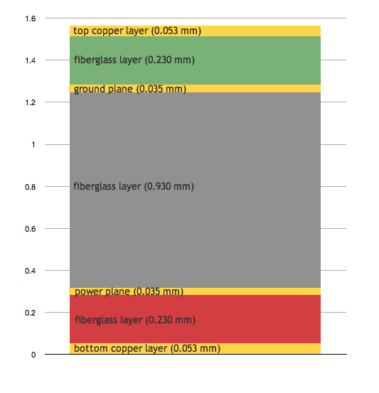
The thickness of the green layer (which is actually yellow in real life) means that a 5 mil wide trace has a characteristic impedance of 80-85 ohms. In theory, I could match this impedance with termination resistors near the memory chips to insure that signals don't reflect in nasty ways, but because the memory errors look like timing problems rather than noise from reflections on a few data lines and more parts mean higher costs, I decided not to add them at this point.
My friend Michael has an extremely fast oscilloscope. Using his scope, I was able to take a look at the signals on some of the memory control lines. Here's what they look like. (Apologies for the poor photo-- I wasn't intending to show it to the world.)
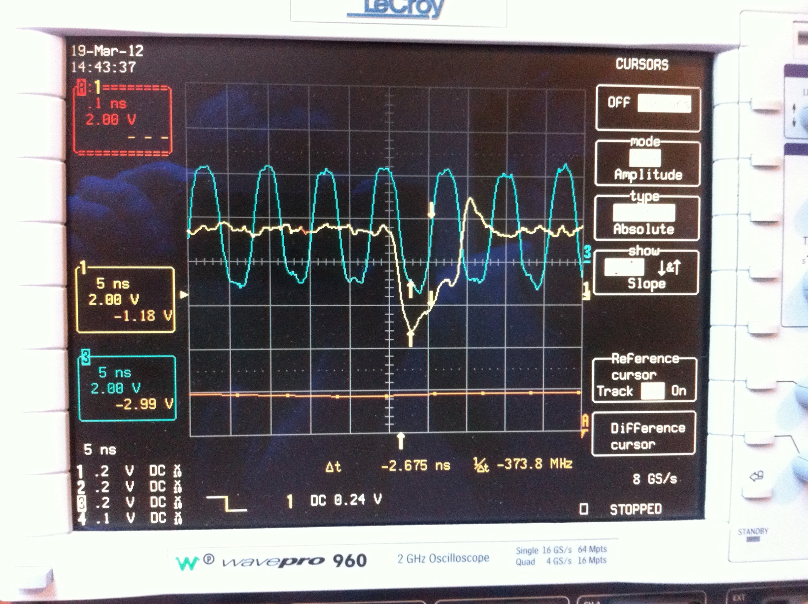
The whole screen shows shows two signals for 1/20,000,000th of a second. The green line is the 133 MHz memory clock pulse. The yellow line is the write-enable signal, which pulses low to signal that a write is taking place.
So what the hell does this picture mean? A rough summary is, "That yellow line looks like a noisy mess." In more precise terms, after the green signal crosses the minimum logical high voltage of 2.0 V (AKA VIH,MIN), we need the yellow signal (write enable) to stay below the maximum legal logical low voltage, 0.8 V (VIL,MAX) for 0.8 ns. You can't tell exactly from this picture, but the yellow signal rises right when the required hold time elapses. In theory, it should work, but given how noisy the signal is, it seems likely that it might slip to the wrong side of the line some of the time.
How do we fix it?
To make the memory timing work right, I wanted to do two things at the same time-- I wanted to make sure all the signals arrive simultaneously and that they're not jammed so close together that currents in one trace induce noise in adjacent traces.
To make the traces the same length, I delved into the fetid depths of the Altium API via Jscript. After Altium emitted the length of each leg, I added them together with a quick Python script. (I'll include the code at the bottom of the post.) This gave me a CSV file that allowed me to calculate the average and standard deviation of the net lengths.
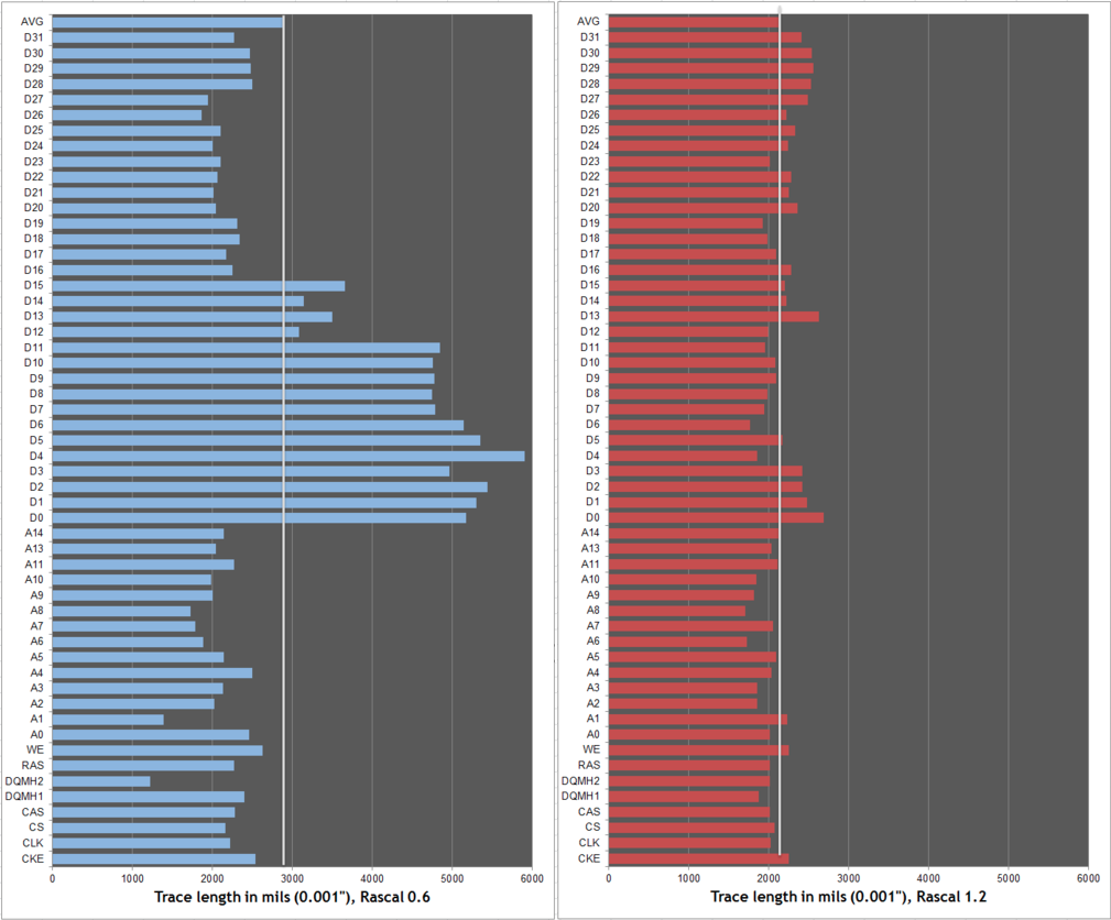
With the help of this tool, I redid the connections between the RAM and the processor with even trace lengths. For the original Rascals, I laid the board out without particular attention to signal integrity. The average memory trace was 2.91 inches with a standard deviation of a whopping 1.24 inches. For Rascal 1.2, the average trace was reduced to 2.15 inches and the standard deviation was 0.23 inches. The picture below shows the original Rascal in blue on the left and the new version in red on the right. You can see that the blue version looks crazy; in the red version, the longest mismatch relative to the clock line roughly 5x better at around 0.7 inches, which corresponds to a delay mismatch of 0.1 nanoseconds.
I also rearranged the decoupling capacitors to minimize the length of their connections to the ground and power planes. I tried to space traces at least 6 mil apart from each other to minimize crosstalk between them. I could have done a more serious analysis of the trace spacing to minimize crosstalk, but as with termination resistors, I opted not to do it until I know I have to. My original, naive Rascal design worked, even though my traces were drastically different lengths, crammed together, and varying in impedance, so my hope is that a layout that doesn't do anything really stupid will succeed.
Rascal 1.2 on the way
The Rascal 1.2 PCBs have been sent out for assembly in Colorado; I should have the new Rascals back later this week. If they work, I'll have a larger batch up for sale in a few weeks as I already have the PCBs. Otherwise, Rascal 1.2 be cursed, and on to Rascal 1.3!
UPDATE
I got the new Rascals today (May 2, 2012) and they work. I haven't tested them 100% yet, but they both booted correctly, passed a few minutes of memory testing (~1 trillion write/read cycles without error) and loaded a bunch of files in the editor without a hitch.
Code
Here's the Jscript code for talking to Altium; feel free to do whatever you want with it. I'd recommend deleting it and then destroying all storage media it may have tainted.
var Board; //IPCB_Board;
var Net;
var Iterator;
var ReportFile;
var address_lines = ["A0","A1","A2","A3","A4","A5","A6","A7","A8","A9","A10","A11","A13","A14"]; // A12, A15+ omitted deliberately
var data_lines = ["D0","D1","D2","D3","D4","D5","D6","D7","D8","D9","D10","D11","D12","D13","D14","D15","D16","D17","D18","D19","D20","D21","D22","D23","D24","D25","D26","D27","D28","D29","D30","D31"];
var control_lines = ["CKE","CLK","CS","CAS","DQMH1","DQMH2","RAS","WE"];
var term_res_lines = ["NetRA3_1","NetRA3_2","NetRA3_3","NetRA3_4","NetRA4_1","NetRA4_2","NetRA4_3","NetRA4_4","NetRA5_1","NetRA5_2","NetRA5_3","NetRA5_4","NetRA6_1","NetRA6_2","NetRA6_3","NetRA6_4"]; // NetRA1* and NetRA2* omitted deliberately
var more_res_lines = [,"NetRA7_1","NetRA7_2","NetRA7_3","NetRA7_4","NetRA8_1","NetRA8_2","NetRA8_3","NetRA8_4","NetRA9_1","NetRA9_2","NetRA9_3","NetRA9_4","NetRA10_1","NetRA10_2","NetRA10_3","NetRA10_4","NetRA11_1","NetRA11_2","NetRA11_3","NetRA11_4","NetRA12_1","NetRA12_2","NetRA12_3","NetRA12_4","NetRA13_1", "NetRA13_2","NetRA13_3", "NetRA13_4", "NetRA14_2", "NetRA14_3"];
var critical_nets = address_lines.concat(data_lines, control_lines, term_res_lines, more_res_lines);

if (!Array.prototype.indexOf) {
   Array.prototype.indexOf = function(item) {
      var i = this.length;
      while (i--) {
         if (this[i] === item) return i;
      }
   }
}

FileName = "C:\Net_Length_Report.Txt";

fso = new ActiveXObject("Scripting.FileSystemObject");
ReportFile = fso.CreateTextFile(FileName, true);

function ShowBusLength(){
    Board = PCBServer.GetCurrentPCBBoard;
    Iterator = Board.BoardIterator_Create;

    Iterator.AddFilter_ObjectSet(MkSet(eNetObject));
    //Iterator.AddFilter_NetClass("U5-signals");
    Iterator.AddFilter_LayerSet(AllLayers);
    Iterator.AddFilter_Method(eProcessAll);
    Net = Iterator.FirstPCBObject;

    while (Net != null) {
        if (critical_nets.indexOf(Net.Name) >= 0) {
            ReportFile.WriteLine(Net.Name + "," + CoordToMils(Net.RoutedLength));
        }
        Net = Iterator.NextPCBObject;
    }
    ReportFile.Close();

    ReportDocument = Client.OpenDocument("Text", FileName);
    if(ReportDocument != null)
        Client.ShowDocument(ReportDocument)
}
Here's the Python script for summing lengths of multi-leg nets.
import csv

r = csv.reader(open('net-length-report.csv', 'rb'))
d = {}
for line in r:
     d[line[0]] = line[1]
d['zero'] = '0.0'

outfile = open('output.csv', 'wb')

buses = [
    ('A0','NetRA11_1'),
    ('A1','NetRA11_2'),
    ('A2','NetRA11_3'),
    ('A3','NetRA11_4'),
    ('A4','NetRA12_1'),
    ('A5','NetRA12_2'),
    ('A6','NetRA12_3'),
    (you get the idea-- there were more nets listed here)
]

for leg1, leg2 in buses:
    total = float(d[leg1]) + float(d[leg2])
    outfile.write(leg1 + ',' + str(total) + '\n')

outfile.close()