Basic tutorial: controlling motors
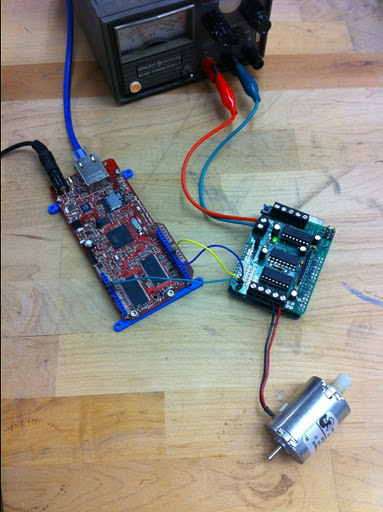
Suppose you want to control a motor through the internet. In this example, I'll explain how to go about it. I'm going to use four devices chained together: a Rascal, an Arduino Uno with a motor control board from Adafruit on top, and a small DC motor.
A little background on motor control
For DC motors, you run the motor by sending a voltage signal that alternates between on and off. To go slowly, the signal is mostly off; as you speed up, the signal is more on and less off. This is called "pulse width modulation." You can read more details about this on the Arduino PWM page.
For stepper motors, which are used more for positioning tasks, like driving a printhead in a printer, the signals sent to the motor are more complex. Typically, there are 4 wires, and they each carry square wave signals out of phase with each other. The image below shows a few different schemes that are used.
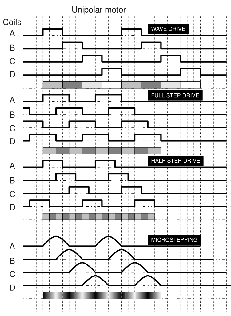
(Image from the stepper motor page on Wikipedia.)
With both types of motors, the pulses are very fast-- each one lasts around 1 ms. With the Adafruit motor shield code and an Arduino with a 16 MHz crystal, the exact PWM frequency is 16,000,000/64/256 = 976.6 Hz. (The 64 divisor is a prescales the system clock down to produce the timer clock, which rolls over every 256 steps, so that we can have 256 different PWM levels, but you don't need to understand the details.)
Because the pulses are so fast, we'll dedicate the Arduino to the motor control and do all the internet stuff on the Rascal. In this example, the Arduino will be mostly idle because controlling a single motor is easy, but if you were trying to do smooth control of multiple motors, the Arduino wouldn't have time to deal with any internet stuff. In general, it's desirable to separate the fast stuff like motor control from large, slow tasks, like most kinds of network communication.
Communicating with the Arduino
Of course, we need to be to pass commands from the Rascal to the Arduino if we want the motor to react. For noise immunity, we want to use a digital bus. We could use I2C, SPI, or a serial port, but I2C wins because its bus-addressable, meaning that we can chain multiple Arduinos together and address them individually if we want to.
Here's the code we'll run on the Arduino. We'll use the Wire library to listen to the I2C bus. The rest of the code consists of functions from the Adafruit motor library.
// Motor number 1 (Front) is 29 hex or 41 decimal
AF_DCMotor motor(4);
int x=0;
void setup()
{
    Wire.begin(0x29);              // Set I2C address in hexadecimal notation
    Wire.onReceive(receiveEvent);  // Set up interrupt handler
    motor.setSpeed(200);
    motor.run(FORWARD);
}
void loop()
{
    motor.setSpeed(x);
}
void receiveEvent()
{
    x = Wire.receive();    // receive byte as an integer
}
The code has three functions: setup(), loop(), and receiveEvent(). The first two are standard for the Arduino; you might look over the bare minimum Arduino tutorial if you're new to this. The third function is what's called an interrupt service routine or interrupt handler-- it's a function that is executed whenever a new I2C message arrives.
Most of the time, the Arduino will just run through the main loop, repeatedly setting the motor speed to the last value of x. Whenever a new message comes in from the Rascal, the receiveEvent() handler will be triggered. We'll take the number delivered by I2C and store it in x. The next time through the main loop, that value will be passed to setSpeed().
Setting up the Arduino for motor control
The electrical setup here is straightforward.
-
The motor shield plugs into the Arduino.
-
The DC motor hooks to the connector labeled M4.
-
A 9 V power supply connects to the external power connector ("EXT_PWR") on the shield. (Make sure that the PWR jumper on the shield is closed, like it is out of the box.)
Then we need a web page to send speed data to the Rascal. We start with an empty
divand then use the jQuery UI library to make a slider.
<h1>Motor control demo</h1>
<div id="slider"></div>
The Javascript below does two things. The first function turns our empty div into a slider with a range of 0-255. The second function makes the slider send out a GET request to /i2cset every time we let go of the slider. Before the GET goes out, it reads the "value" option of the slider and adds it into the target URL. If the slider were at near halfway (say 125/255) when it was released, it would generate a GET request to /i2cset/0x29/125/0/C
<script type="text/javascript">
$(function() {
    $( "#slider" ).slider({ min: 0, max: 255 });
});
$( "#slider" ).bind( "slidestop", function(event, ui) {
    var value = $( "#slider" ).slider( "option", "value" );
    $.get("/i2cset/0x29/" + value + "/0/C");
});
</script>
The Javascript GET request generated by the code above gets mapped by the Rascal's web framework to an I2C function by this code.
@public.route('/i2cset/<addr>/<reg>/<val>/<mode>')
def i2cset(addr, reg, val, mode):
    from pytronics import i2cWrite
    res = i2cWrite(int(addr), int(reg), int(val), mode)
    print '## i2cset ## {0}'.format(res)
    return str(res)
This makes the Rascal's I2C hardware send out a message to a device (0x29, in our example) containing the data 125. When the Arduino hears this on the I2C bus, it says , "Ooh! 0x29! That's me!" It grabs the 125 and sets the motor speed appropriately.